
 TR
TR  EN
EN 
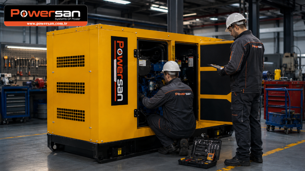
When a production line stops, the loss is rarely limited to a few minutes without power. Interrupted processes, rejected product, restart time and delivery delays can all add to the cost. In a data centre, a power event can affect data integrity; in a hospital, it can affect the continuity of critical equipment. For many facilities, the generator set is therefore not simply standby equipment but an active part of the business-continuity chain.
A common sizing mistake is to total the connected load, add a fixed safety margin and select the generator set from that figure alone. If motor starting behaviour, UPS and drive harmonics, load sequencing, ambient temperature and altitude are ignored, a set that appears adequate on paper may not meet the actual site requirement. The catalogue rating is only one part of the calculation. The way the load behaves matters just as much.
|
At a Glance |
|
Industrial generator selection involves far more than choosing a kVA value from a catalogue. Load profile, motor starting, power quality, duty rating, fuel logistics, installation conditions and maintenance strategy need to be considered together. This guide connects the design calculation with real operating behaviour and explains how poor sizing, inadequate ventilation or weak maintenance practices can translate into avoidable downtime. |
Industrial Generator Selection
Key Engineering Criteria for Reliable Backup Power
1. System Configuration: Open-Type or Canopied?
In an open-type generator set, the engine, alternator, radiator and auxiliary equipment remain accessible on the base frame. Where the generator room has been properly designed, this arrangement can provide good service access for filter replacement, belt inspection and alternator connections. It also offers greater flexibility for project-specific silencers, ventilation ductwork or remote-radiator arrangements on larger installations.
A canopied generator set places the engine-alternator assembly inside an enclosure intended to limit noise and provide environmental protection. This can be practical for construction sites, logistics facilities, outdoor plant areas or sites without a dedicated generator room. “Canopied”, however, does not guarantee the same acoustic performance or environmental resistance in every product. Enclosure design, corrosion protection, air inlet and discharge geometry, silencer arrangement, site conditions and the distance used for sound measurements all need to be considered.
|
Field Note Positioning a canopied generator too close to a wall can allow hot radiator discharge air to recirculate into the cooling-air inlet. The set may appear normal at light load, yet become unable to reject enough heat as the load rises, eventually triggering a high coolant-temperature shutdown. The problem is not always engine capacity; airflow design can be the limiting factor. |
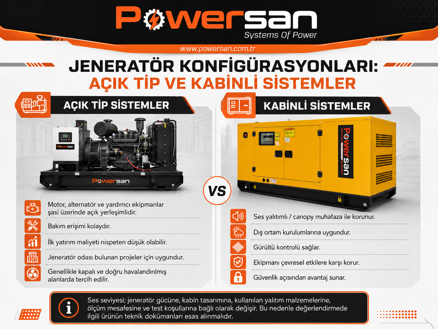
Maintenance access, environmental conditions and acoustic requirements should be considered together when choosing between open-type and canopied configurations.
2. Power Sizing: kW, kVA and Actual Load Behaviour
kW represents active power, while kVA represents apparent power. Many three-phase industrial generator sets are rated at a reference power factor of 0.8, with the relationship kW = kVA × power factor. That relationship is useful as an initial check, but final sizing must also consider the actual power factor, efficiency, harmonic content and connection sequence of the loads.
A facility may have 600 kW of connected load without requiring a 600 kW generator if all loads do not operate at the same time. The reverse can also occur. A system with a much lower steady-state demand may still require additional generator capacity, or a different starting strategy, if a large motor is started direct-on-line and creates a severe transient voltage or frequency dip. The load schedule should therefore distinguish continuous, intermittent, motor, electronic and critical loads.
Motor nameplate kW alone is not enough. Direct-on-line, star-delta, soft-starter and variable-frequency-drive starting methods can produce very different starting kVA and transient behaviour for the same motor. UPS systems, rectifiers, variable-speed drives and some welding equipment can also draw non-sinusoidal current, creating additional alternator heating and voltage waveform distortion. In these applications, alternator sizing, reactances, short-circuit behaviour and the AVR/excitation system need to be evaluated together.
|
Practical Scenario In a crushing plant, sequencing conveyor motors can keep the transient demand under control. If the control system starts all motors at once, the generator may experience a voltage and frequency dip severe enough for contactors to drop out, even though each motor could operate normally once running. The right answer is not always a larger generator; sometimes it is better load sequencing. |
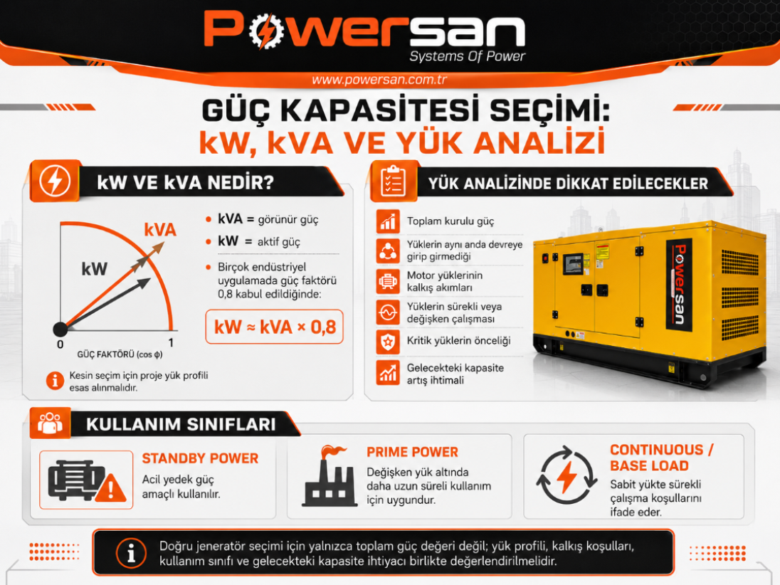
Generator sizing should consider active power, apparent power, power factor and the way loads are connected to the set.
3. Duty Ratings and Transient Load Acceptance
Two generator sets with the same kVA value can be rated for different operating duties. ISO 8528-1 and manufacturer data sheets distinguish ratings such as Emergency Standby Power (ESP), Prime Rated Power (PRP) and Continuous Operating Power (COP) for different service conditions. ESP is intended for standby service during a reliable utility outage, PRP for long-duration operation with variable load, and COP for defined continuous operating conditions. Permitted operating hours, average load and overload capability must be checked against the exact rating definition and the manufacturer’s data sheet.
Transient performance is especially important in data centres. A UPS may bridge the initial interruption, but the generator set still needs to reach stable voltage and frequency quickly, accept the specified block loads and, in a parallel architecture, synchronise reliably. Cummins, for example, uses a manufacturer-specific Data Center Continuous (DCC) rating on certain data-centre generator products. Data-centre ratings from different manufacturers should not be assumed to represent identical conditions; the published load profile, duration and application limits must be checked for the selected product.
Load acceptance depends on more than engine power. Turbocharger and fuel-system response, rotating inertia, alternator electromagnetic characteristics, excitation system, AVR response and controller settings all influence the transient result. On critical projects, single-step load acceptance, voltage and frequency deviation, and recovery time should be checked against manufacturer test data and the project acceptance criteria.
|
Engineering Note Oversizing a generator so far that it spends most of its operating time at very low load is not a sound way to provide for future growth. Extended low-load operation can reduce diesel-engine operating temperatures and contribute to deposits, soot accumulation and wet stacking. The acceptable minimum load is engine- and manufacturer-specific. Where the project justifies it, a parallel-generator architecture can provide a more flexible route to future capacity. |
4. Fuel Selection, Emissions and Emerging Solutions
Diesel generator sets remain widely used for industrial standby power because fuel can be stored on site and the technology is available across a broad power range with strong transient capability. Fuel quality and storage conditions are as important as tank capacity. Water, sediment or microbial contamination in stored fuel can restrict filters and impair fuel-system performance.
Natural-gas and biogas generator sets can suit longer-duration operating scenarios where the gas supply is dependable. A pipeline supply can reduce the need to store large quantities of liquid fuel on site. Gas pressure and quality, continuity of gas supply during a utility outage, engine transient response and the applicable emissions requirements still need to be confirmed at the design stage. An emissions advantage should not be assumed from fuel type alone.
Exhaust-emissions requirements can affect engine selection, aftertreatment, maintenance planning and installation space. On systems fitted with SCR, DEF/AdBlue consumption and logistics need to be planned. DPF-equipped systems require attention to regeneration conditions and exhaust temperature, while oxidation catalysts and other aftertreatment components have their own manufacturer-defined service requirements. Local regulations and the engine’s certified emissions level must be checked together.
Renewable paraffinic fuels such as HVO can be an option for reducing lifecycle greenhouse-gas emissions where an appropriate supply chain is available; this does not mean that tailpipe CO₂ falls by the same proportion. Before use, the engine or generator-set manufacturer’s approval, accepted fuel specification and any model-specific derate or service requirements should be confirmed. Hybrid systems that combine solar or wind generation, battery storage and a generator can reduce generator running hours, but the energy-management strategy, battery charging logic and acceptable engine load range need to be engineered carefully if the expected operating benefit is to be achieved.
5. Alternator, AVR and Power Quality
The engine produces mechanical power; the alternator converts that power into electrical energy. Selecting a generator by engine brand while treating the alternator as secondary is therefore a serious omission. Insulation class, enclosure protection, winding design, temperature-rise limit, short-circuit behaviour and capability with non-linear loads should all suit the application.
The AVR monitors alternator output voltage and regulates the excitation system. When load changes suddenly, voltage can deviate for a short period; the AVR and excitation system help restore it towards the target value. In facilities with sensitive electronic loads, this transient behaviour can be as important as steady-state voltage regulation. PMG-fed AVRs or auxiliary-winding excitation can, in suitable alternator designs, help isolate the excitation supply from the effects of non-linear loads and support motor starting. The correct arrangement depends on the load profile and manufacturer data.
UPS systems and variable-speed drives can draw non-sinusoidal current. Current harmonics can increase alternator heating, raise neutral-current levels and distort the voltage waveform. The solution may involve a larger alternator, a design with suitable reactance characteristics or generator-compatibility data from the load manufacturer. There is no single universal “harmonic load factor” that can be applied to every non-linear load; the application should be assessed from its harmonic current spectrum and kVA characteristics.
|
Field Note If a generator is stable at no load but produces a voltage alarm when a UPS is connected, the AVR is not automatically at fault. The UPS input rectifier, alternator short-circuit/reactance characteristics and AVR settings may be interacting poorly. Measuring the waveform and transient response with suitable power-quality equipment is a better first step than replacing components by assumption. |
6. Control Systems, ATS and Synchronisation
A generator controller is more than a start/stop display. Depending on the controller and application, it can monitor oil pressure, coolant temperature, speed, battery voltage, phase voltages, current, frequency, power factor, active and reactive power; manage protective thresholds; and store event records. During fault analysis, the sequence of events leading up to the final alarm can be as valuable as the alarm itself.
An Automatic Transfer Switch (ATS) selects the appropriate source and transfers the load between utility power and the generator. When utility power fails, the generator receives a start command. Transfer takes place after the engine reaches rated speed and generator voltage and frequency are within the accepted range. When utility power returns, the source is allowed to stabilise before retransfer; the generator then completes its configured cool-down period before stopping. Timing settings should match the facility process and equipment requirements.
Where multiple generator sets operate in parallel, voltage, frequency, phase sequence and phase angle must be matched within the control system’s permitted tolerances before closing onto the bus. Once synchronised, active-load sharing is managed through the engine speed/fuelling control and reactive-load sharing through the excitation/AVR system. Incorrect current-transformer polarity, phase-sequence errors or incompatible control settings can lead to reverse power, circulating reactive current and poor load sharing.
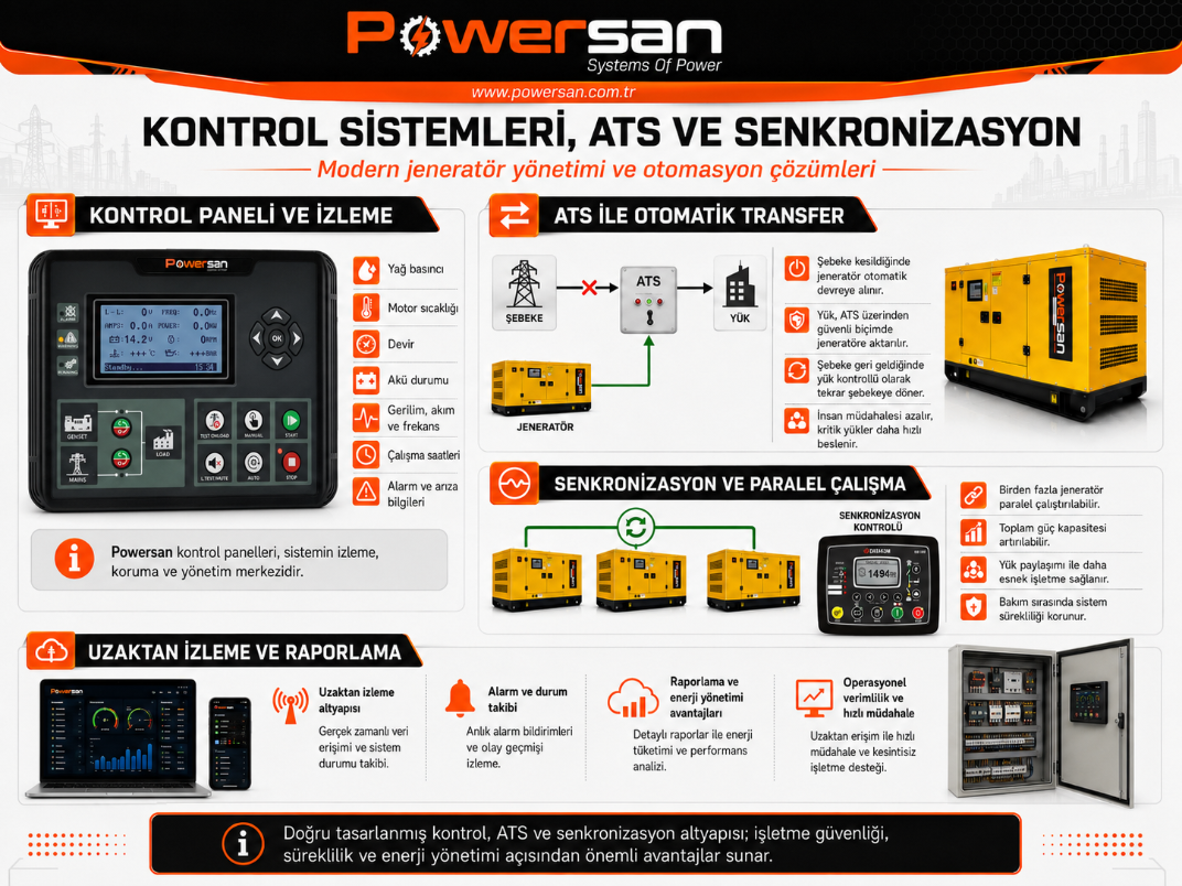
Generator control, ATS, synchronisation and remote-monitoring layers form part of the same power-management architecture.
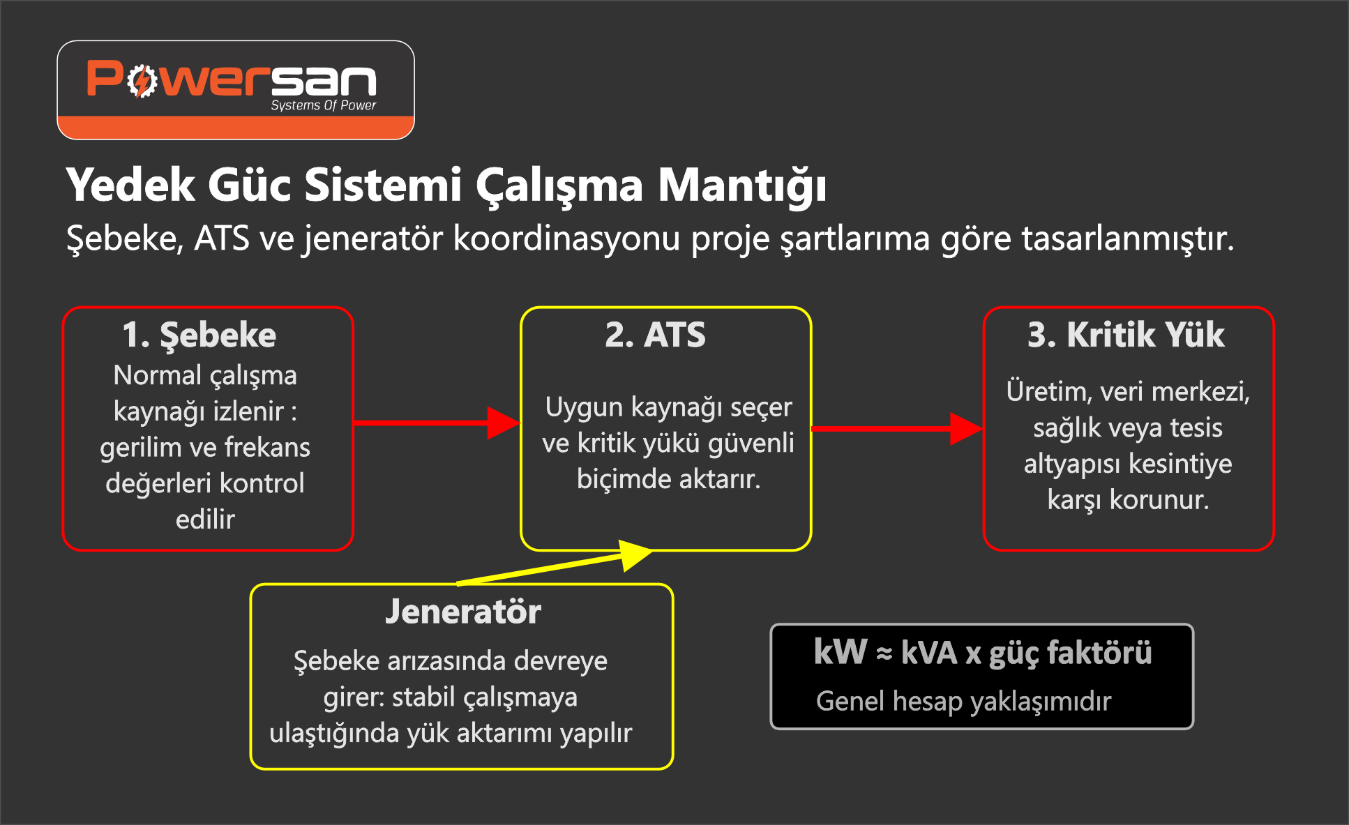
The transfer logic between utility power, ATS, generator and critical load should be engineered for the project requirements.
7. Installation: Where Generator Performance Is Won or Lost
A correctly selected generator can still become unreliable through poor installation. Foundation capacity, vibration-isolator arrangement, service clearances, cable routing, exhaust back pressure, fuel piping and ventilation design need to be treated as one system. The generator room should be engineered while the equipment is being selected, not after it has been placed on site.
A large wall opening alone does not guarantee that radiator discharge air will leave the room effectively. Inlet area, duct losses, louvre and acoustic-attenuator resistance, prevailing wind direction and other room heat sources should be considered. Excessive bends, inadequate pipe diameter or an unsuitable exhaust run can push engine exhaust back pressure beyond the permitted limit, causing performance loss and high exhaust temperature. The engine manufacturer’s allowable back-pressure limit should govern the design.
Available engine and alternator output can fall as altitude and ambient temperature increase. These derating values should come from manufacturer data rather than estimates. A set that is adequate at sea level may not carry the same load with the same performance at a high-altitude, high-temperature site. Dust, humidity, salt and corrosive or chemical atmospheres may also require different filtration, coatings or enclosure protection.
Earthing and neutral arrangements must be designed together with the protection system. The choice between three- and four-pole transfer switching, whether the neutral is switched, generator-star-point earthing and residual-current/protection arrangements depends on the site distribution system. This cannot safely be copied from a generic diagram; the project engineer needs to evaluate the earthing system, fault levels and protection coordination together.
|
Practical Check Can every service door open fully? If a radiator or alternator has to be removed, is there a practical route to take it out of the room? Does access to a fuel filter require a technician to work beneath a hot exhaust line? Questions that are ignored on the drawing can become expensive and unsafe problems on maintenance day. |
8. Commissioning, Testing and Planned Maintenance
Commissioning is not simply starting the engine and confirming nominal output voltage. Phase sequence, protective settings, ATS timings, emergency stop, fuel and cooling-system checks, battery charging, remote signals and electrical/mechanical values under load should be verified. Where required by the project acceptance plan or applicable standards, the installation should be tested progressively with facility load or a suitable load bank and the results recorded.
Running a generator at no load does not, by itself, verify full operating performance. The engine may run, but the alternator, fuel system, cooling system and exhaust system do not experience real load conditions. If facility load cannot be used safely, a load-bank test can be performed in accordance with the manufacturer and project procedures. Voltage, frequency, load, oil pressure, coolant temperature, relevant exhaust values and alarm/event records should be monitored during the test.
The starting battery is a critical component whose available capacity reduces with age and condition. A charger may appear normal while a weak battery still suffers excessive voltage drop during cranking. Fuel and air filters, engine oil, coolant, belts, hoses and electrical connections should be maintained according to the manufacturer’s running-hour and calendar intervals. Heavy dust, high ambient temperature, low utilisation or long standby periods may require the maintenance approach to be adjusted.
|
Example Fault Scenario A generator that has been exercised only at no load may still experience low fuel pressure when a significant load is applied, even with a full tank. One possible cause is sediment or contamination accumulated during storage restricting the filter when fuel flow increases. In that situation, tank level alone is not enough: fuel condition, filter restriction, supply pressure and operation under load should all be checked. |
9. Pre-Project Checklist
| Check | Key question to answer |
|---|---|
| Load profile | Which loads are continuous and which are intermittent? What is the largest single-step load? |
| Motor starting | How are the motors started, and in what sequence? |
| Electronic loads | Are harmonic and generator-compatibility data available for UPS systems, drives, rectifiers or welding equipment? |
| Duty rating | Is the set for emergency standby only, or will it operate as prime/long-duration power? |
| Site conditions | What are the altitude, temperature, humidity, dust, salt/corrosion and noise limits? |
| Fuel logistics | What runtime is required, how will the tank be sized and filled, and how will fuel quality be monitored? |
| Transfer and controls | Are ATS timings, remote monitoring, BMS/SCADA interfaces and alarm scenarios defined? |
| Maintenance access | Is there safe access to filters, batteries, radiator, alternator and connection points? |
| Test plan | How will commissioning and periodic load testing be carried out, what are the acceptance criteria, and what records will be retained? |
The Operational Impact of Correct Engineering
The right generator is not simply one that can carry the nominal load. It should start within the planned outage sequence, remain within acceptable limits during transient load changes, operate correctly with the site protection and transfer architecture, and allow the maintenance team to reach the equipment safely.
Open-type or canopied configuration, duty rating, fuel, alternator, control system, ATS or synchronisation requirements, site installation and maintenance strategy are not independent decisions. A reliable generator system emerges when these factors are engineered together around the actual load profile and the operating conditions of the project.